
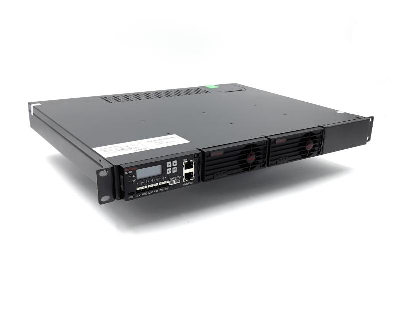
PS-56v3000w
The purpose of the manual is to help you quickly and effectively navigate the installation and functions of your new Power Over Ethernet Power Supply.
Our goal is to make our products as intuitive and simple to use as possible, so we value your feedback and questions directly to us at service@poetexas.com. Phone +1-512-479-0317.
Or you’re always welcome to leave questions or comments on our product page: PS-55v3000w.

What’s Inside
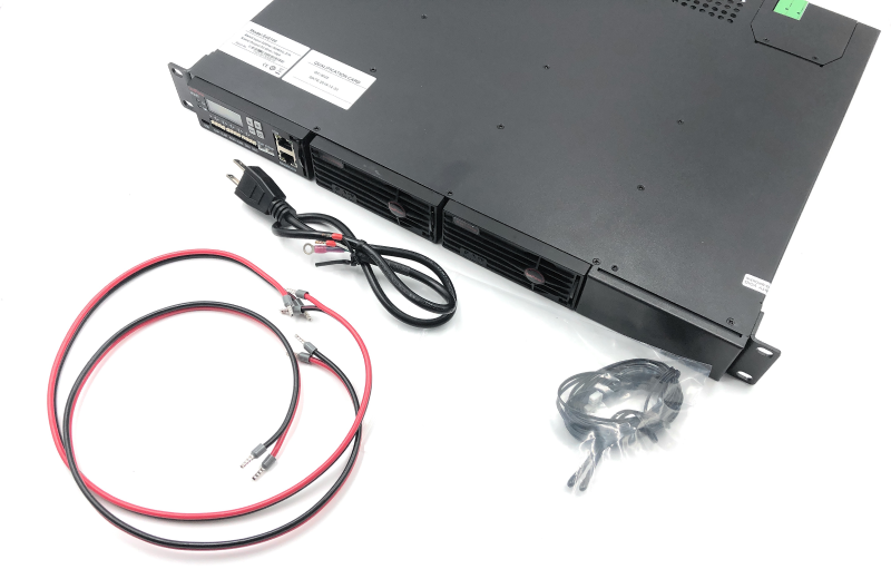
- 1 X MANAGED POWER SUPPLY
- 2 X 12 AWG DC POWER CABLES
- 1 X AC POWER CABLE
- 1 X TEMPERATURE SENSOR WIRE KIT
WHAT YOU NEED:
- 4 X RACK MOUNTING SCREWS AND NUTS
- PATCH CABLE TO CONNECT TO THE SWITCH FOR MANAGEMENT
* The kit has the supplies necessary to power the GBT-24-M up to a full 2,000 watts
General Installation
NOTE: The injector includes the screws for the rack wings, but it does not include the rack mounting nuts or screws. So, you’ll want to grab some of those.

Rack Installation

Wiring the Power Supply
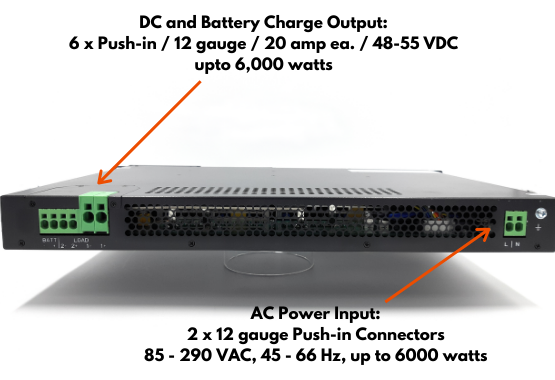
SELECTING THE POWER SOURCE: This power supply can draw more than 2,000 watts of power. A typical 15 amp, 120 VAC circuit breaker will trip at 1,800 watts. If you just plug it into a regular 15 amp circuit with other lights and outlets, it will draw enough power to trip the breaker. For a full lighting application, it requires a dedicated 20 amp circuit.
STEPS:
- Ensure power is properly disconnected from the wiring to the device
This may mean either keeping the included AC cable unplugged or shutting off the breaker to the circuit.

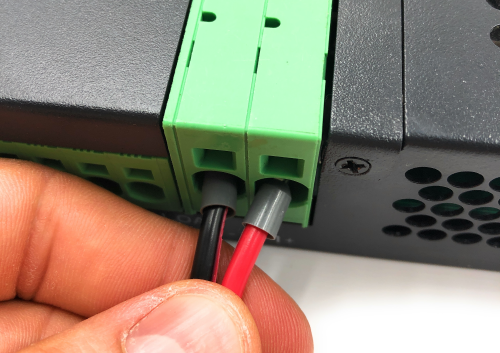
- Connect the AC power to the AC input.
“L” is typically a black wire
“N” is typically a wire wire
Ground is typically green
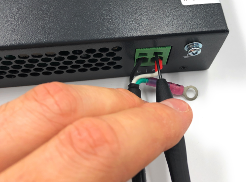

Don’t forget to ground the cable and the power supply.
Now you can wire the DC side of the power supply.
DO NOT CONNECT POWER TO THE DEVICE YET.
Configuration
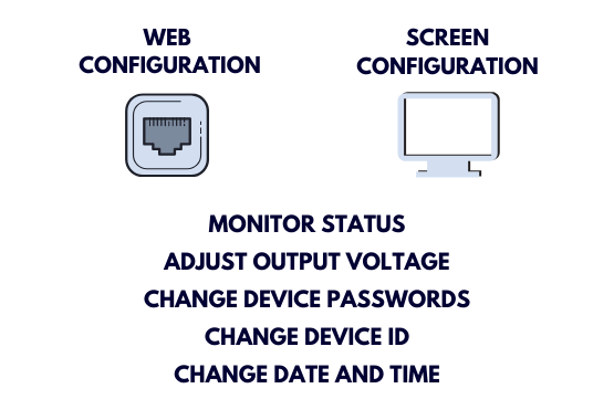
In this manual we’ll cover the details for the on-screen and web interface. If you’d like to see the manual for the other configuration methods, you can find it here:
SUPER TECH MANUAL – PS-53v3000w
In this manual we’ll demonstrate how to navigate the onscreen and web interface to be able to:
- Monitor the status of the device
- Adjust the output voltage
- Change the device passwords
- Change the device ID
- Change the device Date and Time
- Change the IP address
Operating The LCD Screen
Change the Charge and Output Voltage
Follow these steps:
Click the return button to enter the Menu ↵
Right arrow to navigate to Settings →
Return button to enter the Menu ↵
Return button to enter the Password ↵
Return button to enter Batt Settings ↵
Up arrow to navigate to Charge Settings ↑
Return button to enter Charge Settings ↵
Return button to edit ↵
Right arrow to navigate to Place Holder →
Up arrow to change settings ↑
Back arrow when finished ⊂
View Status
Simply click the right arrow (>) to scroll through:
Main Display – Date, Volt In, Volt Out, and Total Load
Battery Status
Temperature – Battery and Ambient
Inverter Status – Not used in this configuration
Alarm Status – Inverter (not used) and System Status
Change the System Configuration:
Follow these steps:
Click the return button to enter the Menu ↵
Right arrow to navigate to Settings →
Return button to enter the Menu ↵
Return button to enter the Password ↵
Right arrow twice to navigate to Settings → →
Return button to enter the Sys Settings ↵
Up arrow to change password to 1000 ↑
Return button to enter the Password ↵
To Change the Passwords:
Right arrow to select Password 1 →
Right arrow twice to select Password 2 → →
Up arrow to select the password ↑
Return button to edit ↵
Use th up and right arrows to edit ↑ →
Return button to finish ↵
Back to Sys Settings ⊂
Right arrow to navigate to Date →
Up arrow to change settings ↑
Back arrow when finished ⊂
Web Management
CONNECTING TO THE CONSOLE
The PS-53v3000w has a web-based management interface that can be accessed through the console port on the front of the power supply. Before you integrate it into your network, you will need to configure the device such as setting the date and time, IP address, and username and passwords.
First you need to connect the console port on the front of the power supply to a computer. If you don’t have an ethernet port on your laptop, this works just fine with an ethernet to USB adapter.Then power on the power supply. The settings will remain in the device even if you power it off and power it on again.

I’m giving the instructions here for a Windows computer. If you need help doing this on a MAC, simply go to YouTube and search on setting an fixed IP address for a MAC. Then use the IP address information I give below.
In Windows, navigate to your Network and Sharing Center. If you don’t know how to get there, simply click on the Window button on the bottom left and type “Network and Sharing Center”.
When it comes up, you should see an ethernet connection. If not, double check 1) you’re connected to the injector, and 2) the injector is powered on.Click on the ethernet connection. It will bring up a dialog box.Click “Properties” on the bottom left.
In the next dialog box, look in the middle for “Internet Protocol Version 4”. Click on it, then click “Properties” in the bottom right.
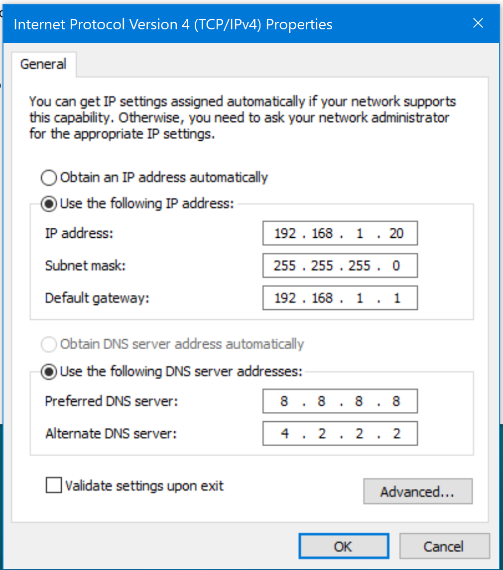
Click: User the following IP address
IP Address: 192.168.1.20
Subnet Mask: Sets itself
Default Gateway: 192.168.1.1
Preferred DNS Server: 8.8.8.8
Alternate DNS Server: 4.2.2.2
Hit Okay to close this dialog, then Okay one more time.
I’ve tried not hitting okay the second time, and I couldn’t get it to connect. So, make sure it hit okay to close out the two dialogs.
Then navigate to 192.168.1.190.
The video below will take you through the rest of the configuration.
Technical Specifications
Product Specifications
| AC Plug Connector Type | Spring Cage Clamp 12 AWG |
| Adapter length | 3 ft |
| Cable connector length | 2 ft |
| Certifications | CE, FCC, UL |
| Dimensions | 19 x 13 1/4 x 1 3/4 in |
| Display Type | LCD |
| Efficiency | >90% at full load |
| Input Frequency Range | 45 – 65 Hz |
| Input Voltage Range | 85-290 VAC |
| Management Port | 1 |
| Max Current | 40 amp |
| Max Power for Kit | 6000 watts at 200 VAC, 3000 watts at 120 VAC |
| Max Voltage | 42-58 volt DC |
| Mount Type | Rack |
| Operating Temperature Range | -40 – 55 degrees C |
| Output Voltage | 53 Volts |
| Power Supplies | Hot Swappable Dual Rectifiers |
| Weight | 13 lbs 12.2 oz |