
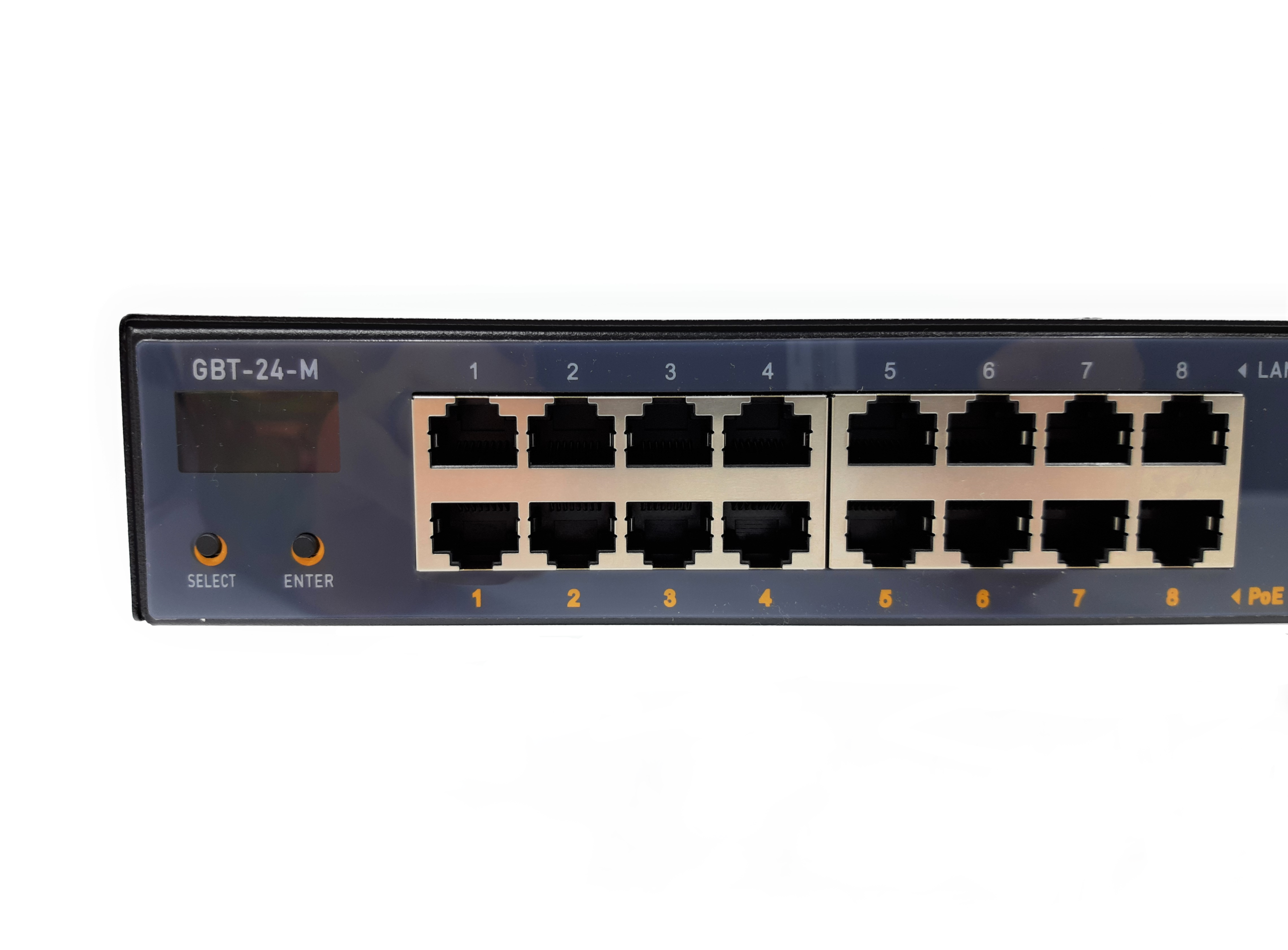
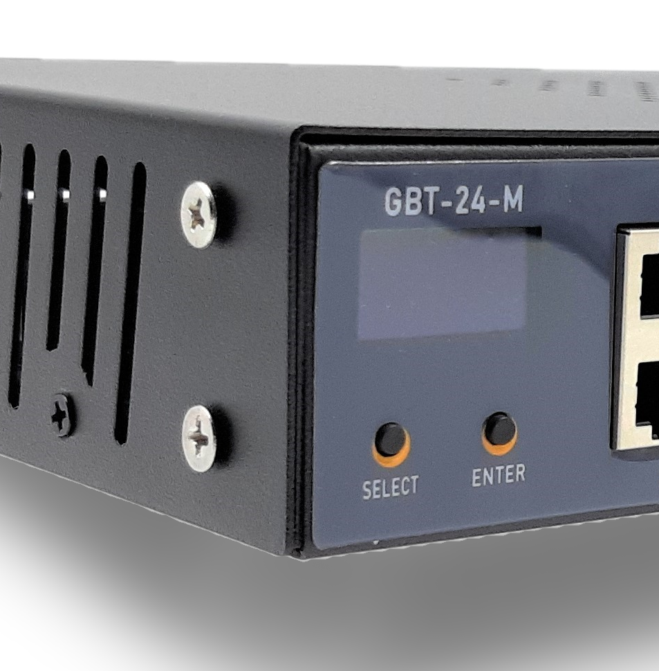
GBT-24-M
Welcome to the PoE Texas Manual for the 24 port Layer 1 Managed 4 Pair PoE Injector!
The purpose of the manual is to help you quickly and effectively navigate the installation and functions of your new Power Over Ethernet Injector.
Our goal is to make our products as intuitive and simple to use as possible, so we value your feedback and questions directly to us at service@poetexas.com. Phone +1-512-479-0317.
Or you’re always welcome to leave questions or comments on our product page: GBT-24-M.
What’s Inside
PARTS LIST:
- 1 X MIDSPAN INJECTOR
- 2 X RACK MOUNT BRACKETS
- 8 X SCREWS (FOR RACK MOUNT)
WHAT YOU NEED:
- 4 X RACK MOUNTING SCREWS AND NUTS
- 24 X 6″ PATCH CABLES TO CONNECT TO THE SWITCH PORTS
- POWER SUPPLY* AND/OR TERMINATION CABLES
* The GBT-24-M does not have an integrated AC-DC power supply to give you power flexibility. See the section on About the Power Supply.
General Installation
Your new PoE injector is designed to be simple to install and set up. You should only need at most a Philips head screw driver and a patch cable for the management console.
NOTE: The injector includes the screws for the rack wings, but it does not include the rack mounting nuts or screws. So, you’ll want to grab some of those.
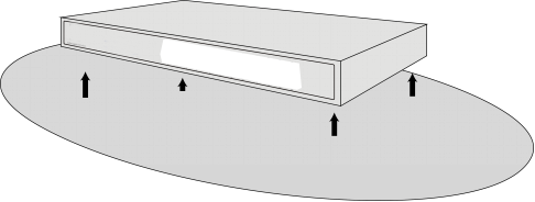
Desktop Installation
The GBT-24-M doesn’t have much of a “desktop” application, however, you can set it on a desk or a shelf. The unit requires ventilation on the sides and top for maximum efficiency, so we do not recommend stacking other equipment directly on top of it.
You can use stand off feet on a product above it to give room for air circulation.
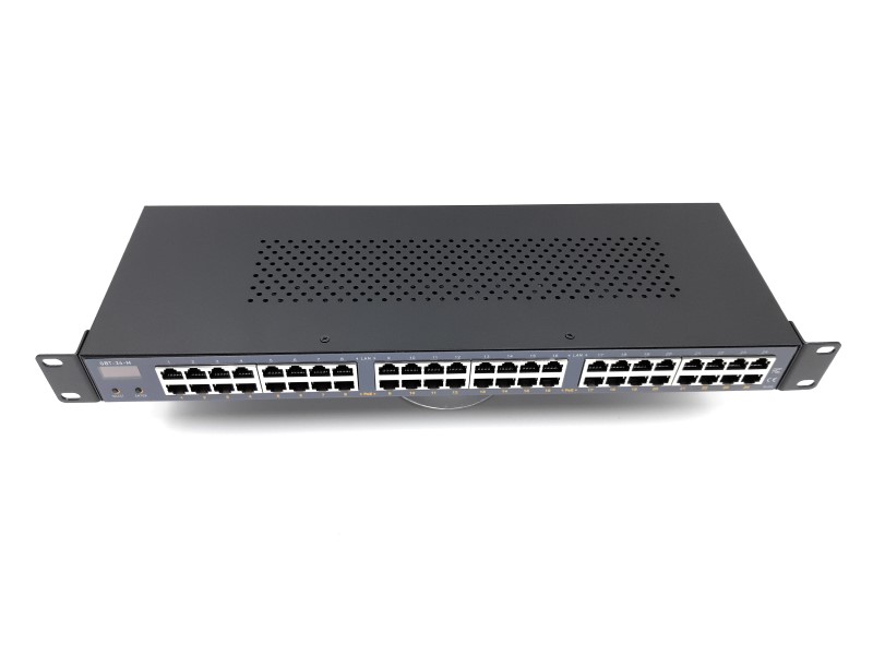
Rack Installations
The injector comes with brackets for a 19″ rack configuration. Please contact us if you need a different rack. It DOES NOT come with the nuts and screws to mount the injector onto the rack. You’ll need to get those.
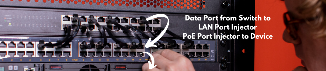
Also, a midspan injector DOES NOT manage data. You need one network switch port for each port of the midspan injector. So . . . get at least 24 x 6″ patch cables to connect the GBT-24-M to the switch ports.
It’s what we call ONE to ONE. Want to learn the difference between an injector and a switch? Check it out here.

- Using the 8 x small screws provided in the box, attach the two rack brackets to either side of the switch so that the brackets face the front as in the image above
- Using rack screws and nuts (not provided) mount the switch into the rack space (the switch will use 1u of rack space)
- Plug the switch into an outlet
- Start plugging in your PoE and non-PoE devices
About the Power Supply

The GBT-24-M is designed to take 48-55 volt DC power. You’ll notice there are multiple input power points on the back. DON’T PANIC!
The injector can take power into any one of the termination points and share the power with all of the ports.
We’ve provided multiple power terminations for your convenience and to ADD MORE POWER!
Here’s how you can power the injector:
Option 1: DC barrel jacks. Each DC jack has a 5 amp limit. You can use this with normal power bricks with a 5.5 x 2.1 mm dc barrel at 48 volts with less than 240 watts. There are two of them, so you can add a second powe brick to reach 680 watts using the DC barrel jacks.
Option 2: Push-in terminal sockets. These have a 20 amp limit and are rated for 12 AWG wire. We recommend crimp on ferrules to make inserting and removing the cable easier. You can use 1 x set of 12 gauge wire to power up to 960 watts. As you go up above 960 watts in total power draw, you will need to use a second port. Above 1,920 watts, you will need to add a third input power cable.
NOW YOU’RE COOKING WITH GAS!
HOW DO I KNOW HOW BIG MY POWER SUPPLY SHOULD BE?
You can use our PoE calculator to quickly calculate your expected load on the PoE injector.
Check it out here:
We do offer the 24 port managed midspan with a 6,000 watt (at 240 volt) managed rectifier for your convenience.
Check it out here: PS-55v3000w
Configuration
The following sections will show you how to use either the OLED screen on the front of the GBT-24-M or the web-based management console found on the back. This section will talk briefly about what you can configure and manage with your GBT-24-M.
PORT CONFIGURATION:
You have three OIS Layer 1 settings you can manage by portwith this injector:
- On / Off: You can force the port to power off or power on
- Active / Passive: You can configure the port to use active IEEE 802.3 style negotiation to enable the port or you can set the port to passive and have power on all the time
- Mode A / Mode A+B: You can choose whether the port will output:
– Mode A: 2 Pair PoE with maximum power of 25 watts for active or 30 watts for passive
– Mode A+B: 4 Pair PoE with maximum power of 60 watts for active or 80 watts for passive
BUT WHAT DOES THAT ALL MEAN? See our PoE Tutorial Here
USE CASES AND RECOMMENDED PORT CONFIGURATIONS:
PoE Lighting or Automation
On
Active: 60 watt or less load
Passive: 80 watt or less load
Mode A+B
High Powered Point to Point or Point to Multi Point Communication
On
Passive
Mode A+B
Voip Phone, Wifi Access Point, PTZ Camera (IEEE 802.3at)
Default configuration
On
Active
Mode A
DEVICE CONFIGURATION
LOGIN CREDENTIALS:
You can modify the admin name and password
Default Username: admin
Default Password: admin
Please change that for your security
You can also create a User name and password without access to change the device configuration.
Default User Username: useradmin
Default User Password: user
DEVICE IP ADDRESS / ID
The device’s ID is it’s IP address which can be customized to fit your network’s IP set up.
The device does not ask for a dynamically assigned IP address, so you will have to give it a fixed IP address.
PORT NAMES
You can create 7 character long names for each of the ports to make identifying and managing the device connected to that port easier.
You can find details on how to set these configurations in the sections below.
Operating The LCD Screen
Main Display
When you plug in the PoE injector, it will automatically boot up to the main monitoring page. This screen gives you a great heads up display on the PoE situation with the whole injector.
So why make a PoE injector with a display like this since it’s already managed? We’re considering the smart building situations where networks and infrastructure aren’t always in place when you need to start installing and testing new PoE devices such as lighting, displays, or sensors. This display screen allows a user to see and manage the PoE on devices without having to have the full network installed and turned up.

So what does it all mean?
Top Row: This displays the IP address of your device so you can quickly reference where to go to find the management webpage
Second Row: The output voltage of the injector
– So you can confirm what power your devices should be receiving and update your load calculations on the PoE calculator
Third Row: The total output current of the injector
– So you can confirm your total load
Fourth Row (First number): The total power consumption of the injector
– So you can measure and monitor your total power consumption
Fourth Row (Second number): The temperature inside the device
– So you can monitor temperature and avoid overheating
Button Navigation:
Navigating to a PORT: From the main screen simply press the “Select” button. You will arrive at PORT 1 which will blink. If you’d like to manage PORT 1, simply push the “Select” button. Otherwise, press the “Enter” button to scroll through the ports. Once you’ve arrived at the port you’d like to manage, press the “Select” button.
Go Back to Previous Port: If you’d like to go backward between ports, press and hold the “Enter” button for 2 seconds.
Go Back to Main Screen: If you’d like to go back to the main screen, press and hold the “Select” button for 2 seconds.
Changing a PORT Configuration: Once you’re at the port you’d like to configure, simply press “Select” until the setting you would like to change is blinking. Once the setting is blinking, press “Enter” to change the state. Once you’re done configuring, you can hold the “Select” button to return to the main screen.
- ON / OFF – This allows you to turn the current port on or off
- Active / Passive – This allows you to decide whether you want the port to do the IEEE PoE negotiation (active) or simply output power all the time (passive)
- Mode A / Mode A+B – This allows you to decide whether to limit the port to 30 watts with 2 pair PoE or to allow the port power 60 or 80 watts using 4 Pair PoE
By default each port is set to Active IEEE 802.3at (30 watt) 2 Pair PoE. For lighting applications you will need to change it to Mode A+B for 60 watt devices. If you need the full 80 watts, you’ll also need to set the port to Passive.
Want to learn more what those settings mean? See our PoE Tutorial Here.

Other Important Controls: From the main menu screen:
- Pressing and holding the “Select” button for 3 seconds will cause the injector to soft reboot.
- Pressing and holding the “Enter” button for 5 seconds will toggle the temperature from Celcius to Fahrenheit.
- Restore to Factory Default: Pressing and holding “Select” and “Enter” for 3 seconds will restore the injector to factory default settings.
Web Management
CONNECTING TO THE CONSOLE
The GBT-24-M has a web-based management interface that can be accessed through the console port on the back of the injector. Before you integrate it into your network, you will need to set the IP address to match your network settings.
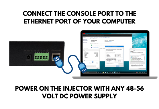
All you need to do is connect the console port on the back of the injector to a computer. If you don’t have an ethernet port on your laptop, this works just fine with an ethernet to USB adapter.
Then power on the injector using any 48-56 volt power supply. The settings will remain in the device even if you power it off and power it on again.
Now comes the techiest part of the process. You will need to disconnect your computer for wifi and the internet. I know this feels very dangerous, but it’s only for a moment.
I’m giving the instructions here for a Windows computer. If you need help doing this on a MAC, simply go to YouTube and search on setting an fixed IP address for a MAC. Then use the IP address information I give below.
In Windows, navigate to your Network and Sharing Center. If you don’t know how to get there, simply click on the Window button on the bottom left and type “Network and Sharing Center”.
When it comes up, you should see an ethernet connection. If not, double check 1) you’re connected to the injector, and 2) the injector is powered on.Click on the ethernet connection. It will bring up a dialog box.Click “Properties” on the bottom left.
In the next dialog box, look in the middle for “Internet Protocol Version 4”. Click on it, then click “Properties” in the bottom right.
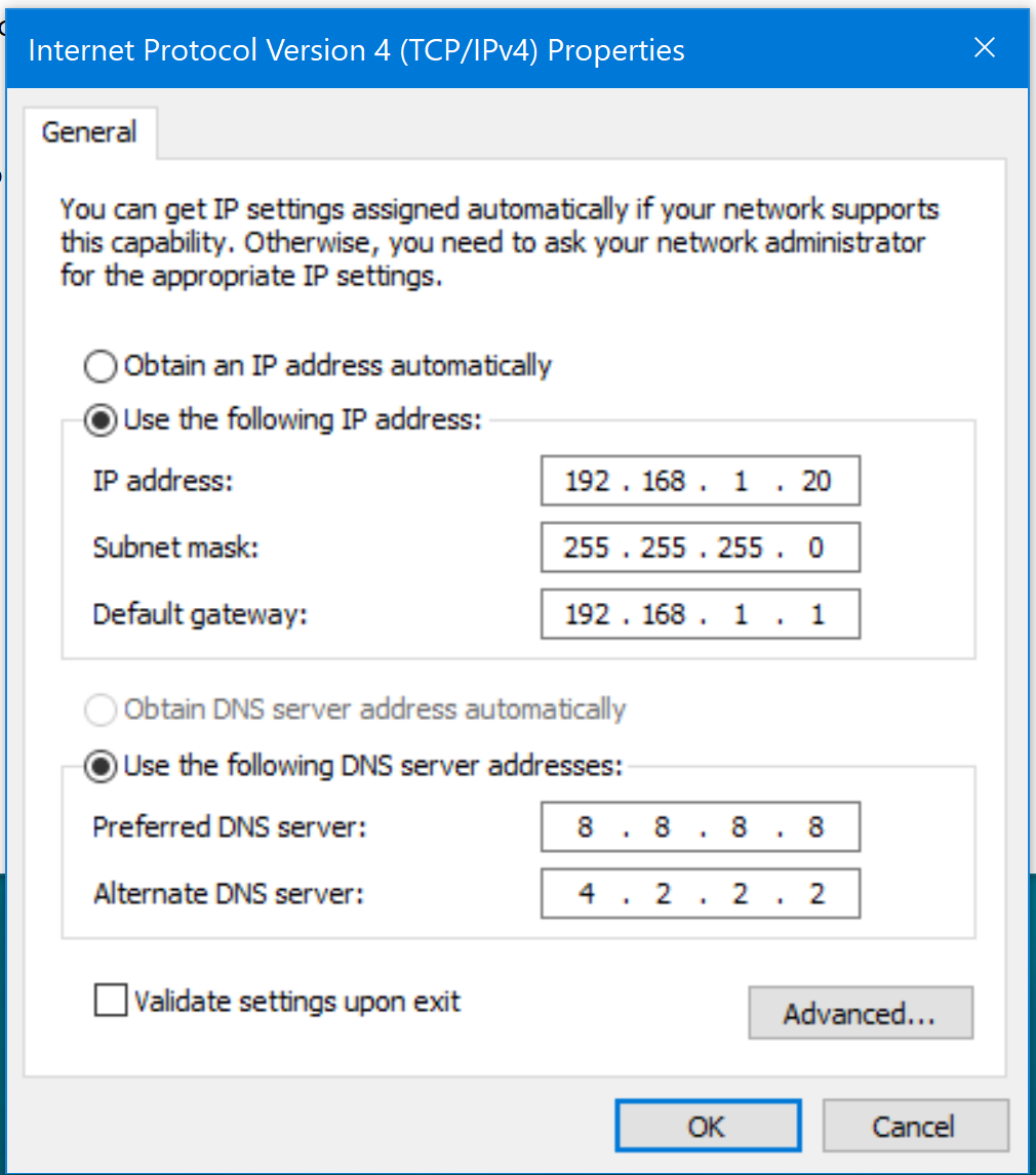
Fill out the fields just like this.
Click: User the following IP address
IP Address: 192.168.1.20
Subnet Mask: Sets itself
Default Gateway: 192.168.1.1
Preferred DNS Server: 8.8.8.8
Alternate DNS Server: 4.2.2.2
Hit Okay to close this dialog, then Okay one more time.
I’ve tried not hitting okay the second time, and I couldn’t get it to connect. So, make sure it hit okay to close out the two dialogs.
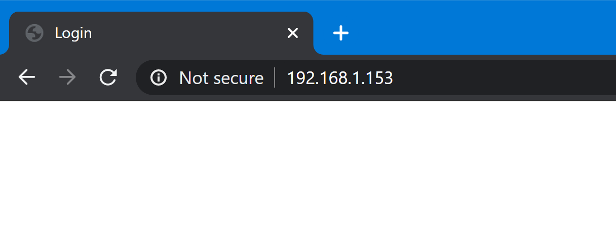
Finally, open a web browser and type 192.168.1.153 in the URL Bar.
The default username is: admin
The default password is: admin
If for any reason you cannot get this to login in during the first set up, simply hold the “Select” and “Enter” buttons on the front of the injector until it resets to factory defaults.

Heads Up Display
Once you’ve logged in, you’ll go directly to the Heads Up Display showing the status of all the ports on the injector. You turn each port on or off as well as see:
- PoE Type: Active or Passive Negotation
- Power Consumed in mA (Current)
- Output Power Potential (Volts)
- Power Consumed in Watts
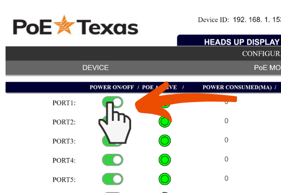

To cycle power on any particular port, simply click the toggle switch next to the port name you’d like to cycle power on.
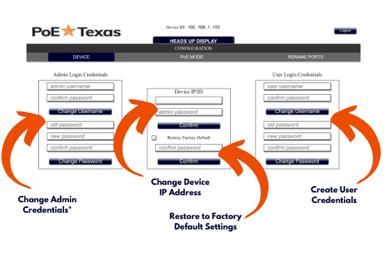
Device Management
- Modify the admin credentials
- Create a user credentials
- Modify the device’s IP address
- Reset the device to factory defaults
The admin credentials allow you to modify the device configuration. A user account allows you to control the ports without changing the device configuration.
Default User Username: useradmin
Default User Password: user
PoE Mode

PoE Mode Page
This page allows you to decide whether to make the port:
- Passive or Active PoE
- 2 Pair or 4 Pair PoE
Active vs Passive PoE:
Active PoE is the traditional IEEE type PoE most devices use that requires a negotiation to turn on power. 90% of POE devices use this type of PoE, so it’s the default setting.
Passive PoE is a non-standard PoE that certain types of Wireless Data technology uses. If you enable it with a non-PoE device connected to the port, it will damage the device. (We don’t expect many people are connecting non-PoE devices to a PoE injector, but strange things happen)
A quick note, though, this injector can output more power in passive mode than in active. So, if you need more power for your PoE device, consider switching it to passive. Speaking of which . . .
2 Pair vs 4 Pair PoE
The difference between these two states comes down to how much power each port requires. 4 Pair PoE allows for double the power on a port:
2 Pair PoE Active
25 watts – Single Signature
2 Pair PoE Passive
30 watts – No signature
4 Pair PoE Active
60 watts – Dual Signature PoE
4 Pair PoE Passive
80 watts – No signature
Rename Ports
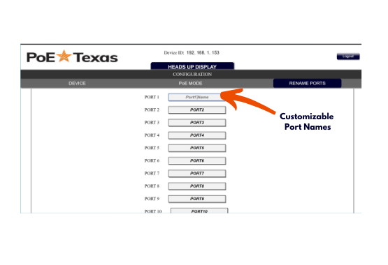
Rename Ports Page
On this page you can relabel how your ports to have customized seven character names to make them easier to manage.
Technical Specifications
Product Specifications
| Data + PoE Ports | 24 |
| Data Ports | 25 |
| Data Rate | Gigabit |
| DC connector | 2 x 2.1mm DC / 2 x Phoenix connectors |
| Dimensions | 1.5 x 19 x 3.5 inches |
| Display Type | OLED |
| Input Voltage Range | 48 – 55 Volts DC |
| Max Power for Kit | 60 Watts (Active IEEE 802.3bt negotiation) / 80 watts (Managed passive configuration) |
| Mount Type | Rack |
| Operating Humidity | 10% to 90% |
| Operating Temperature Range | 0-40 C |
| PoE Method | Active / Passive |
| PoE Mode/Pinout | Mode A / B |
| PoE Standard | IEEE 802.3bt Type 3; 4 Pair PoE; Mode A / B negotiation |
| Weight | 4.5 lbs |